Description
EMC CX3-20 / CX3-20c Storage Array
EMC CLARiiON CX3-20 offers flexible networked storage that’s ideal for mail/messaging, databases, and distributed applications. With the CX3-20, you get a powerful networked storage system based on the CLARiiON CX3 UltraScale architecture.
Scale seamlessly up to 111TB of storage capacity—leveraging the end-to-end 4 Gbps bandwidth of the CLARiiON CX3 UltraScale architecture. Get the price/performance and five 9s availability (99.999 percent) your business needs. Wizard-driven software capabilities make daily management easy and advanced functionality protects your data.
Tap four 4 Gbps Fibre Channel and eight 1 Gbps iSCSI host ports, or a Fibre Channel-only configuration with twelve 4 Gbps host ports.
EMC CX3-20 Pricing
SPS Pros sells used/refurbished and fully-tested EMC storage arrays to help your company meet its storage needs at the best prices available. If you need something you don’t see listed as an option, please use the contact us page and we’ll help you get what you need.
CX3-20 / CX3-20c Major Subassemblies
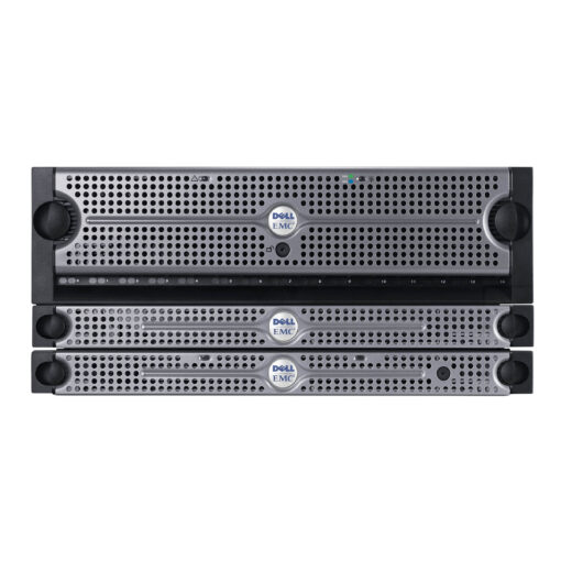
The minimum CX3-20 / CX3-20c assembly consists of a single 1U storage processor enclosure (SPE), a 1U standby power supply (SPS), and a 3U 4Gbps UltraPoint disk-array enclosure (DAE), for a total of 5U. A fully configured CX3-20 / CX3-20c consists of the SPE and dual SPS, plus eight 3U-DAEs, for a total of 26U. Minimum and maximum configurations of the CX3-20 / CX3-20c assembly are shown below in Figure 1.

Figure 1. Minimum and Maximum CX3-20 / CX3-20c Configurations
The dual SPS, SPE, and DAE assemblies are rackmounted for efficiency, and provide the user with many different configuration options. The CLARiiON 40U cabinet (with industry-standard 19-inch racks) can house different configurations of the CX3-20 / CX3-20c systems, as well as 1, 2, or 4Gbps Fibre Channel switches (1U and/or 2U) and/or Ethernet network switches. The standard 40U cabinet comes with four power distribution units (PDUs) and four power distribution panels (PDPs). Power supplies on the left side of the cabinet use the left PDU; power supplies on the right use the right PDU. Additionally, all CLARiiON storage systems can be installed in non-EMC industry-standard cabinets.
CX3-20 / CX3-20c Storage Processor
Each CX3-20 / CX3-20c Storage Processor (SP) contains one 2.8Ghz 1MB L2 cache Intel Xeon processor. This dual-storage processor architecture provides the power for enhanced performance, stability, and reliability in the CX3-20 / CX3-20c storage system. Each CX3-20 / CX3-20c SP has 2GB of system memory. There is a PCI Express-x4 CMI channel between the storage processors that is used for communication and messaging between the storage processors as well for the mirroring of data that is written to the portion of memory that has been designated for write cache on the storage system.

Figure 2. Air Dam of CX3-20 Storage Processor’s Front-End and Back-End Ports
Figure 2 shows the air dam for the CX3-20 storage processor. LEDs provide indications of LAN connectivity, SP power, boot prorgess, and fault status, as well as power supply and blower status. The LEDs also indicate the speed at which the front and back-end ports are running – green indicates 2Gbps and blue indicates 4Gbps.
Each CX3-20 SP has six 4Gbps Fibre Channel front-end (FE) ports. These ports which are small-form-factor pluggable (SFP) optical transceivers, are customer replaceable and have a default setting of auto-negotiate. Using Navisphere Manager or CLI, the user can change the settings from auto-negotiate to 1, 2, or 4Gbps. These Fibre Channel front-end ports may be connected to a 1, 2, or 4Gbps HBA on a server/host.

Figure 3. Air Dam of CX3-20c Storage Processor’s Front-End and Back-End Ports
In addition, the CX3-20c SP (as shown in Figure 3) has four 1Gbps iSCSI front-end (FE)ports as well as two 4Gbps Fibre Channel front-end (FE) ports. Using Navisphere Manager or CLI, the user can change the settings on each 1Gbps iSCSI front-end (FE) port from auto-negotiate to 10/100/1000Mbps. These iSCSI front-end ports may be connected to a 10/100/1000Mbps port on an Ethernet switch, or they may be directly connected to a 10/100/1000Mbps NIC or iSCSI HBA on a server/host.
Each CX3-20c SP also has one 4Gbps Fibre Channel back-end port, which, along with the peer SP, form two redundant FC back-end loops for disk connectivity and capacity expansion.
The CX3-20 / CX3-20c SP also has two 10/100 LAN ports, one for Management and one for Service, as well as two micro-DB9 communication ports, one for serial communication and one for SPS sensing. The Management port is used to access and manage the storage processor via Navisphere, while the Serivce port is a dedicated port to be used by EMC Certifed Proven Professionals, should the need arise for them to access the storage processor when they are onsite.

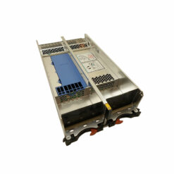
Figure 4. CX3-20 / CX3-20c Power Supplies and Cooling
The CX3-20 / CX3-20c SPE uses four 260-watt power supplies supporting N+1 power and N+1 cooling per storage processor. The power supplies contain thermal sensors for Ambient Over-Temperature monitoring. Cooling is achieved through high speed blowers attached to each power supply module.
A single power supply can power a single storage processor and a single blower can cool a single storage processor. Either storage processors can have a single fault and still maintain write caching. The CX3-20 / CX3-20c can run indefinitely with one power supply/blower module faulted or removed on each SP and still maintain high availability (HA).
CX3-20 / CX3-20c Standby Power Supply (SPS)
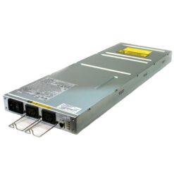
As shown in Figure 5, the CX3-20 / CX3-20c SPE uses two 1-kilowatt SPSs to maintain power to the storage system during a power loss to allow for a full dump of the write cache to a reserved area on persistent disk. In the CX3-20 / CX3-20c, both SPS power output connectors are used to power the SPE as well as the first DAE on the first back-end loop.

Figure 5. View of CX3-20 / CX3-20c Standby Power Supply (SPS)
It is important to cable each SPS so it connects completely to either the A side or the B side. For example, if you are looking at the SPS from the back, they should be configured as follows:
- SPS on the right: Power-out and sense cables should connect to power supply A and SP A.
- SPS on the left: Power-out and sense cables should connect to power supply B and SP B.
If an SPS is cabled with the SPS sense cable going to SP A and the power-out cable going to power supply B (or vice versa), error conditions are displayed when the SPS is tested while it is charging.


Reviews
There are no reviews yet.