Ph: 952-649-3165
How to Upgrade FLARE Code on EMC CLARiiON CX4 Array
Introduction
The following is a series of simple documents aimed at providing visual guidance on the process required upgrade the FLARE code on an EMC CLARiiON CX4 array.
These documents assume that:
- A version of FLARE 30 is already installed on the array (although the steps for FLARE 29 and below are not significantly different)
- You have access to EMC’s Unisphere Service Manager (USM) on a Windows platform
- You have downloaded copies of the FLARE code, Recovery Image and Utility Partition Image.
These documents are not intended as a replacement for EMC’s official procedure guides, and should only be used in conjunction with documentation available from Powerlink (http://powerlink.emc.com). You may also refer to http://www.emc.com/cx4support for customized documentation.
The typical warnings apply when upgrading firmware on an array, particularly if it has valuable data on it. Always perform a back-up first.
Process for Upgrading FLARE Code on an EMC CX4 Array
There are 4 basic steps to complete an upgrade:
- Installing/upgrading Unisphere Service Manager (covered in part 1)
- Preparing for Installation (covered in part 2)
- Upgrading FLARE code (covered in part 3)
- Upgrading the Recovery Image (covered in part 4) and Upgrading the Utility Partition (covered in part 4).
Part 1: Installing Unisphere Service Manager on an EMC CX4
In the past, there was a software installation wizard that could be launched directly from the CLARiiON, but now the requirement is to use EMC’s Unsiphere Service Manager (USM).
This is a client-side application that can be used to perform basic maintenance tasks, including FLARE code upgrades.
Note: This application was known as Navisphere Service Taskbar (NST) prior to the release of FLARE Release 30.
The first step is to install/upgrade USM on the host that will be used to upgrade the array.
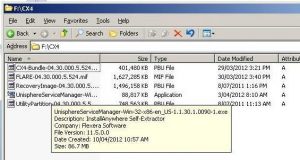
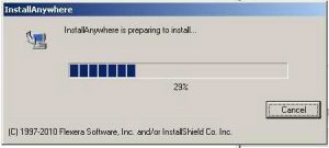
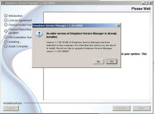
If an earlier version of USM is detected by the installer it will give you the option to upgrade, it is recommended to click Yes.
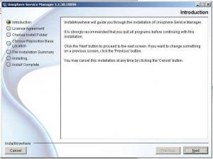
Read through the introduction and click Next.
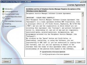
Read through the License Agreement and select “I accept the terms of the License Agreement” and click Next to the continue.
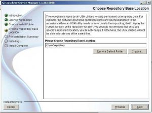
The next step involves the selection of the repository location. This is where USM will store diagnostic data (SP Collects) and items such as FLARE code downloaded from EMC. Use the default options unless there is a particular requirement to store it in a different location.
Click Next to view the Pre-Installation Summary.
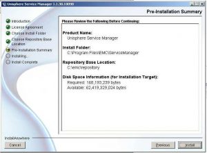
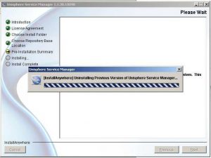
After verifying the information, click the Install button. The old version of USM will be uninstalled.
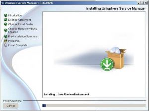
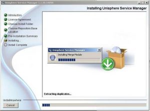
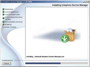
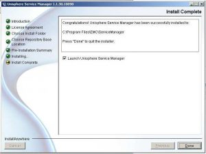
The Installation process will complete, giving you the option to Launch the USM. USM can also be launched from Start>All Programs>EMC>Unisphere>Unisphere Service Manager>Unisphere Service Manager.

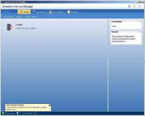
USM will launch with a default Login screen. Click on the Login button.
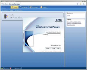
A dialog box will appear requesting details of the array to connect to. This can be a hostname or IP address. Once entered, click Connect to continue.
At this point you’ll then be asked for credentials. You’ll also have the option to select whether you wish to use LDAP authentication, and whether the account you’re using is Local or Global.
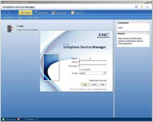
This example uses a global, generic account on a test lab array. Once you’ve entered the appropriate credentials, click Login and USM will login to the array.
Part 2: Preparing for Installation
Once login into USM is successful, you’ll be presented with the following screen:
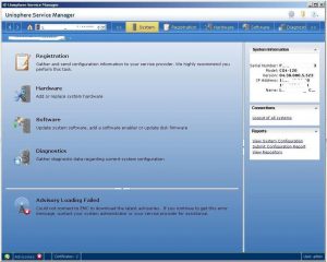
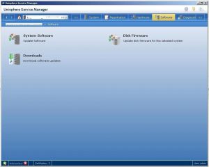
Click on the Software tab to access System Software, Disk Firmware, and Downloads. Click on System Software.
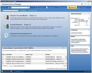
There are three choices under System Software: Prepare for Installation, Install Software, and Download and Install Hot Fix. Click on Prepare for Installation.
A dialogue screen should pop up with an installation wizard.
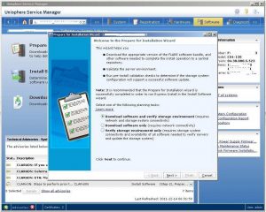
Select “Verify storage environment only” and click Next, as the software has been installed locally.
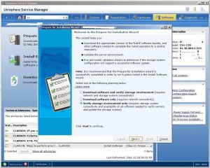
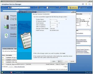
Verify once again that the correct array is logged into. Click Next.
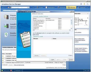
Select the software for Installation. Click Browse.
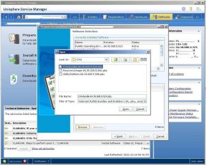
Select the CX4-Bundle that has been downloaded and click Open.
The software is then unpacked and transferred to the array.
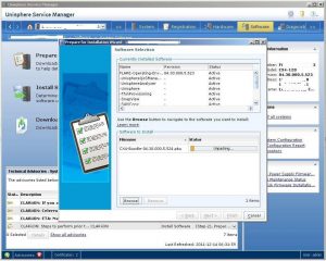
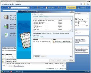
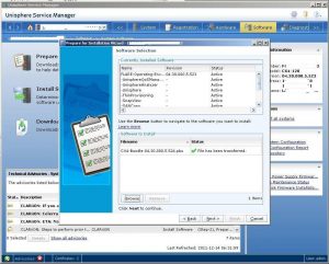
Once the software has been transferred successfully, click Next.
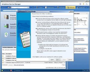
IMPORTANT: A manual check is required for a number of conditions (some of which may be obscure) this is very important to read.
Click Next to continue.
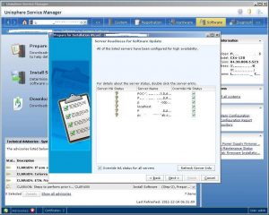
USM then checks that the hosts attached to the array are capable of failover.
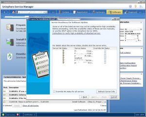
Sometimes, even though the servers are fine, USM won’t be able to accurately gauge the readiness of the servers. Fortunately, there is an Override option, including the standard warning, available to select.
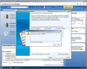
Click Next to proceed.
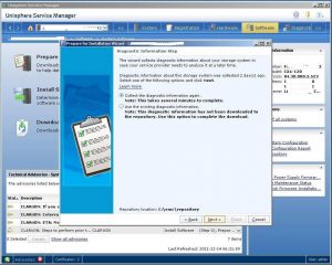
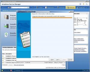
Next is a diagnostic information step. It is generally recommended to let the USM collect the information again. Select “Collect the diagnostic information again” and click Next. This will take a few minutes to complete.
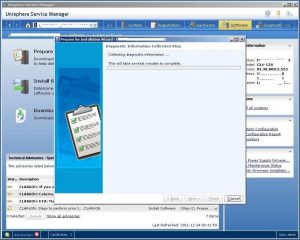
Once this step is complete, click Next.
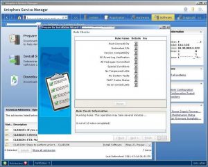
There are a number of rules that are then checked. If any of the checks fail, there will be an option to fix it. This may take several minutes.
NOTE: If it can’t be fixed by USM, speak with your service provider about a fix before the code upgrade is completed.
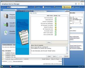
Once completed, if there are only warnings, you can proceed with the installation assuming the warnings are are acceptable. You may click each warning to see more information about it. Click Next to proceed.
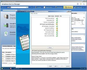
At this point it is necessary to select the NDU delay. It’s suggested you leave this at the default unless there is a good reason to change it. Click Next to continue.
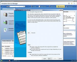
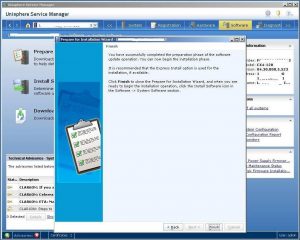
Click Finish to complete.
Part 3: Installing FLARE Code on an EMC CX-4 Array
Once the installation preparation process is completed, click on Install Software (Step 2).
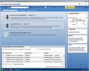
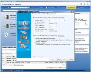
As the Prepare for Installation step has already been completed, there is an option to perform an Express Install.
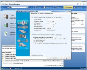
In this example, the Custom Install will be demonstrated to show all the steps that go into upgrading the code. Express installation will be demonstrated further. Click Next to proceed with the Custom Install.
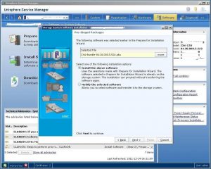
During the previous phase, the software was pre-staged for deployment. Confirm that it is the correct version and click on Next. At this point you could also choose to change the software you’re installing.
Once again, you’ll need to confirm the HA status of the servers attached to the array.
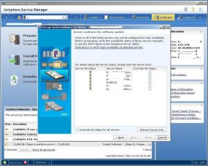
IMPORTANT: Availability issues with these servers must be addressed before continuing.
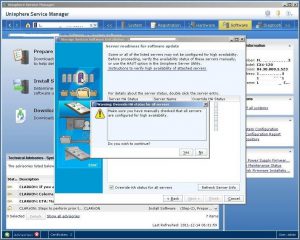
Once any availability issues are addressed, select to override the warning and click Next to continue with the installation.
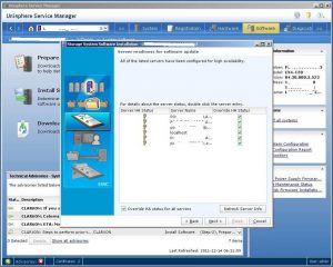
USM will check the repository for diagnostic information.
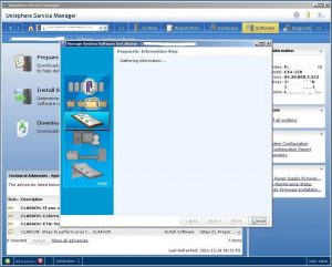
If not long has passed since the Pre-installation and upgrading the software, it should be safe to use the existing diagnostic information.
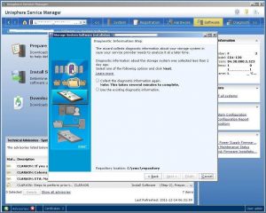
Select “Use the existing diagnostic information” and click Next to continue.
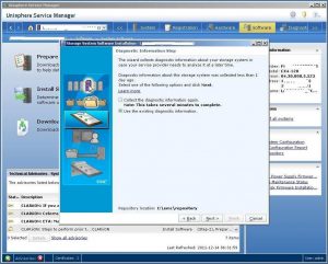
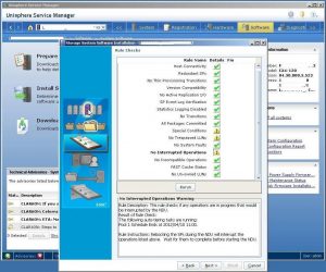
USM then performs a series of Rules Checks to ensure that everything is in order for the installation to proceed.
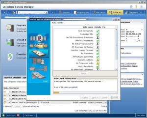
Note: In this example, a scheduled activity will be interrupted by the NDU. While this isn’t a problem for the lab in the example, one should be mindful of such interruptions in a production scenario. If the results of the Rules Checks are satisfactory and there are no Errors, click Next to proceed to the next step.
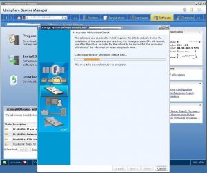
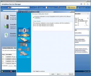
USM then checks that processor utilization on the array is acceptable. The point of this is that, for a period of time while storage processors reboot, all of the array’s workload will be hosted by one SP. If the CPU is already getting belted, it might be wise to re-schedule. This check can be overridden, but it’s not recommended to do this on production arrays.
In this example, the lab array is doing sweet FA, so click on Next to continue.
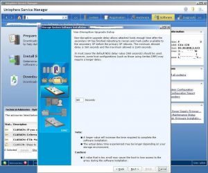
Set the NDU delay here.
Note: The default it is set to 360 seconds, and it is strongly recommended that this setting is not changed unless there is good reason to.
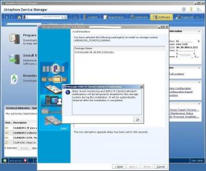
On the next screen you’ll be notified that the ESRS IP Client (also known as CLARalert) will be disabled until the upgrade is complete to prevent false positive alerts to EMC’s triage staff when SPs reboot.
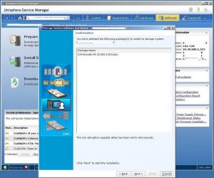
USM is ready to go, so click Next to continue.
This step will take awhile to complete.
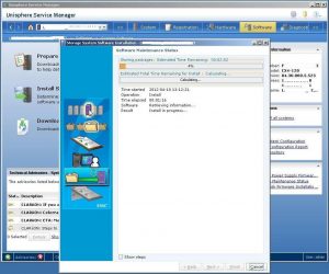
Click on Show Steps to see the steps.
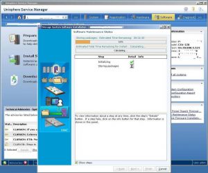
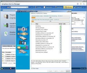
At this point it’s rebooting the Secondary SP (SP B). It always does it on SP B first, in case there’s a problem.
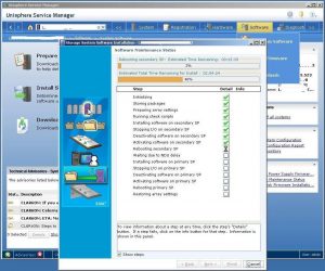
The following shows completion with all green check marks.
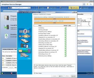
At this point USM offers to commit the FLARE code on the array. While the array is running new code at this stage, if the software is not committed, it is possible to roll the software back.
Note: While you can service I/O while FLARE is not committed,
you can’t do potentially useful things such as bind LUNs, RAID Groups, and Storage Pools. Unless there’s an obvious problem, it’s recommended that you commit to the package. Before you commit the FLARE code, you should check whether the LCC firmware has been successfully upgraded. On a small array with a few DAEs, this won’t take too long. On a larger array (a CX4-960 with 64 DAEs for example) this might take a little longer.
If there are no storage configuration tasks on the horizon, leave it a day or two and make sure there’s no obvious problems. If it’s been upgraded to Release 30.524 to support 3TB drives on the array, and the resources to shut down the drives the moment the code is committed, then you might not be able to wait that long.
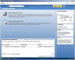
In USM, go to the Diagnostics section. Under the Tools section on the right-hand side of USM, select the “LCC and Power Supply Firmware Update Status” option.
This screen provides information on the status of LCC Firmware (FRUMON) updates that are kicked off by installing new versions of FLARE. Not every version of FLARE has new LCC firmware, but it’s always a good idea to check.
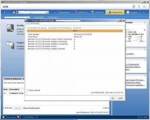
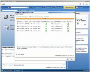
Click on “Show details” to see LCC revisions. Depending on the number and type of DAEs, the time it takes to complete this operation will vary greatly, and can be time consuming.
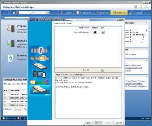
Once the LCC firmware is complete and everything is working as expected, you can commit the FLARE code. To do this, click on the Run button in the Post-install Tasks screen. A warning about write cache will appear, which should not be problematic when completed during a “quiet” period on the array. This process will take awhile to complete.
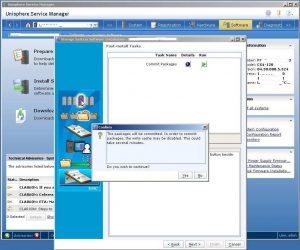
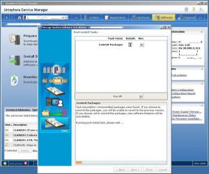
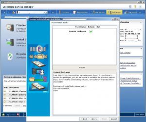
Once it’s complete, there will be a green tick in the Details column and and you may click Next to continue.
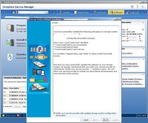
The Finish screen provides information on the completed activities and confirms completion. If your array is registered for support with EMC or a third-party support provider, you can automatically notify them of the upgrade at this point.
Part 4: Installing the Recovery Image and Utility Partition on an EMC CX4
Installing new Recovery Image and Utility Partition is much easier and less time-consuming than upgrading the FLARE.
Installing the Recovery Image on an EMC CX4
To start, click on Install Software. Click Next to continue.
Note: As you have done the Prepare for Installation steps, you won’t have the option to do an Express Install.
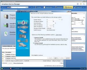
This is basically the same process that you followed for installing the CX4 Bundle, the only difference is selecting different packages. Click on Browse to browse for the Recovery Image software.
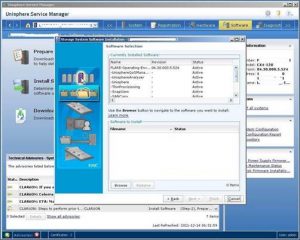
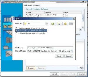
Once the file has been transferred, click on Next to continue.
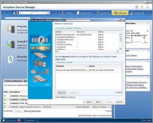
The installation of the Recovery Image and the Utility Partition doesn’t involve any reboots of the SPs, so you’ll find there aren’t quite as many steps to go through. In fact, just verify the correct version of the Image and click Next to continue.
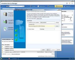
USM loads up the Recovery Image in 12 steps.
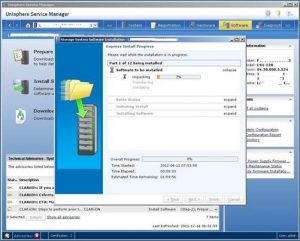
This might take awhile.
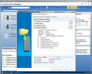
Once done, click Next to finish.
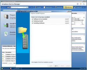
At the Finish screen you’ll get confirmation from USM that the software was installed successfully.
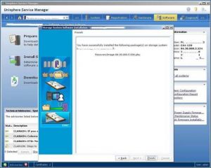
Installing the Utility Partition
Installing the Utility Partition is roughly the same process as installing the Recovery Image. Select the appropriate version of the software to install.
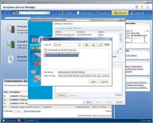
Verify the correct software and click Next.
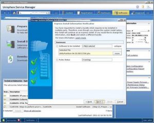
This step shouldn’t take quite as long.
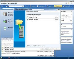
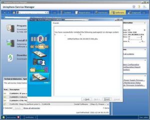
Once it’s done, you’ll get confirmation from USM. Click on Next to finish and complete the process.
At this point, if you’re running Unisphere agents on your hosts, you might look at updating them.
